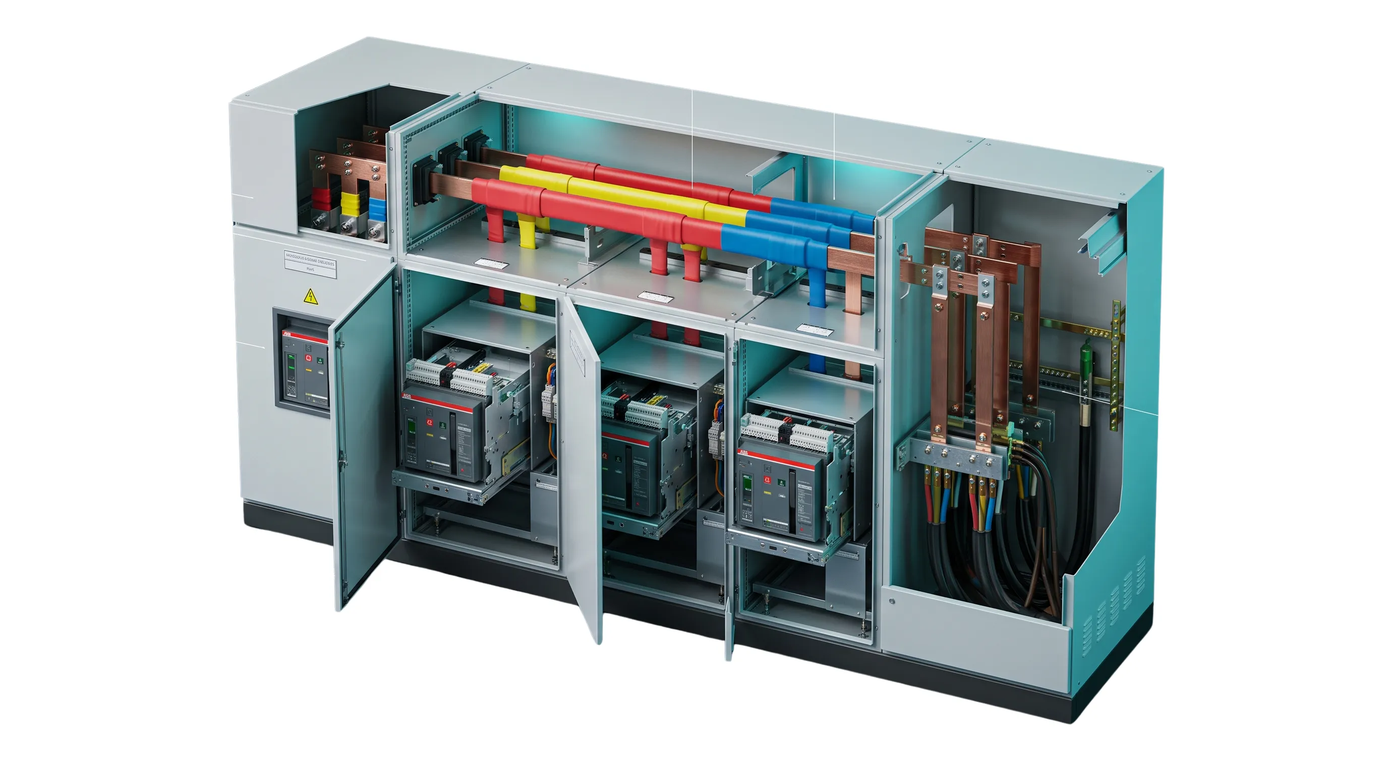
Key Takeaway for MEP Consultants & EPCs
Internal segregation governs operator safety and plant uptime. While Form 1 offers zero barrier separation, Form 3b provides isolated breaker cells with a shared common cable alley. Form 4b isolates both the functional units and external cable termination points into distinct compartments, making it the industry standard for 24/7 continuous operations, automotive plants, and data centers.
Why Internal Separation Matters in Low-Voltage Switchgear
According to IEC 61439-2 (Low-voltage switchgear and controlgear assemblies) and IS/IEC 60947, internal separation divides an electrical enclosure into enclosed compartments using metallic barriers (sheet steel) or non-metallic insulating partitions.
1. Arc Fault Containment
Confines ionized gases and arc flashes to a single cell, preventing cascade burnouts across adjacent circuits.
2. Direct Contact Protection
Shields service engineers from inadvertent contact with energized busbars or outgoing feeder terminals during routine maintenance.
3. Minimizing Plant Downtime
Permits cabling, racking out, or breaker servicing on one branch without shutting down the entire main intake switchboard.
4. Foreign Object Protection
Stops dropped tools, loose hardware, or vermin from migrating into main horizontal or vertical copper/aluminum busbar chambers.
Master Comparison Matrix: Form 1 through Form 4b
| Form of Separation | Busbars vs Units | Units vs Units | Terminals vs Busbars | Terminals vs Other Feeder Terminals |
|---|---|---|---|---|
| Form 1 | No separation | No separation | No separation | No separation |
| Form 2a | Separated | No separation | Same cell as busbars | No separation |
| Form 2b | Separated | No separation | Separated from busbars | No separation |
| Form 3a | Separated | Separated | Same cell as busbars | No separation |
| Form 3b | Separated | Separated | Separated from busbars | Shared common cable alley |
| Form 4a | Separated | Separated | Separated from busbars | Separated (inside unit cell) |
| Form 4b | Separated | Separated | Separated from busbars | Dedicated individual cable chambers |
Form 3b vs Form 4b: The Definitive Comparison
Form 3b Architecture
Functional units are compartmentalized from each other, but outgoing cable terminals share a single common vertical cable alley.
- ✓ Compact enclosure footprint
- ✓ Lower initial fabrication cost
- ✕ Terminating new feeders requires group busbar shutdown
Form 4b Architecture
Functional units are isolated, and outgoing terminals reside in individual, dedicated cable boxes for every feeder.
- ✓ Full hot-work operator isolation during feeder maintenance
- ✓ Mandated for automotive, steel, and continuous cleanrooms
- ! Demands larger electrical room depth & width (~20% increase)
Engineering Nuances: Thermal Derating & Cable Bending Radius
Thermal Entrapment in High Ambient Zones
Form 4b partitions compartmentalize heat. In high summer ambient temperatures across Delhi NCR (45°C–48°C), switchgear inside enclosed Form 4b cells requires temperature rise validation per IEC 61439, busbar derating factors, and IP54/IP55 louvers or forced exhaust systems.
Cable Bending Space Constraints
In Form 4b Type 7 configurations with independent gland plates, terminating large 3.5C or single-core 300/400 sq mm XLPE armored cables requires adequate vertical box depth. Always verify switchboard GA drawings against permissible cable bending radii.
Frequently Asked Questions
What is the difference between Form 4a and Form 4b?
In Form 4a, outgoing cable termination lugs sit in the same physical compartment as the circuit breaker itself. In Form 4b, the cable terminals are isolated in a completely separate, dedicated termination chamber away from the breaker cell.
Can existing Form 3b switchboards be converted to Form 4b on site?
Field modifications to convert Form 3b to Form 4b are rarely practical because Form 4b requires dedicated mechanical partition sheets, individual cable pathways, and pre-engineered clearances verified during factory sheet-metal punching.